

 Current position >About Us
Air Flow Meter Sensors: High-Sensitivity Pneumatic Intake Monitors for Compressed Air
Quick Answer: Silver Automation Instruments supplies air flow meter sensors for compressed air and pneumatic intake lines from DN15 to DN100. The standard output is 4-20 mA plus RS485 Modbus RTU, with a 100:1 turndown ratio and a response time under 1 second. Send us your pressure in bar, temperature in °C, pipe size in DN, and flow range for a quote.
Compressed air is one of the most expensive utilities in a plant. A 1 mm leak on a 7 bar line can waste over 2,000 kWh per year. Most plants do not know where the air is going. Because of this, energy managers install flow sensors at the compressor room and on main branch lines.
We have seen this problem on customer sites many times. A food packaging plant in Malaysia asked us for a sensor on a DN40 compressed air header. The plant operated two shifts at 0.6 MPa. After installing one thermal mass flow meter, they found a continuous night shift flow of 18 Nm3/h even when production was stopped. That flow was a leak. Fixing it saved them roughly 3,100 USD per year.
Which Sensor Type Works for Compressed Air
For compressed air and pneumatic intake monitoring, thermal mass flow sensors are the practical choice. They read mass flow directly. No separate temperature or pressure compensation is needed. This matters because compressed air density changes with pressure and temperature.
Vortex flow meters can work on larger lines. But on small lines below DN25 or at low flow rates, a vortex meter loses signal. Thermal sensors handle low velocity better. A typical insertion thermal probe works from 0.5 Nm/s up to 100 Nm/s. That range is wide enough for most compressed air headers and branch pipes.
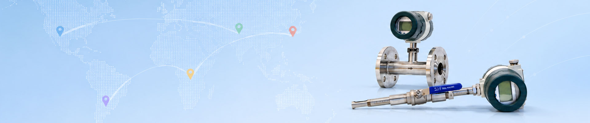
Inline thermal mass flow meters fit DN15 to DN50 lines. Insertion probes suit DN65 and larger headers. In practice, most customers use inline sensors on pneumatic tool drops and insertion probes on main plant air lines.
Key Parameters That Matter on Site
Here is the thing. Air flow sensors must survive wet air, oil carryover, and temperature swings. We specify sensor elements with a stainless steel probe body. The electronics housing is IP65 as standard. Optional ATEX Zone 2 housings are available for gas and chemical sites.
Standard process conditions are 0 to 16 bar and -20 to 60 °C. The flow range depends on pipe size. For a DN25 line at 7 bar, the normal measurable range is 0.5 to 150 Nm3/h. Accuracy is typically plus or minus 1.5 percent of reading plus 0.3 percent of full scale. The sensor response time is below 1 second. That means a PLC can catch a sudden tool upstream trip in real time.
Output choices are 4-20 mA, pulse, and RS485 Modbus RTU. Most engineers choose 4-20 mA for loop power and RS485 for data logging. We also add a PT100 option for temperature output from the same sensor.
Installation Notes for Compressed Air Monitoring
Install the sensor after a straight run. Ten pipe diameters upstream and five downstream is enough for most thermal sensors. Do not install directly after an elbow, valve, or tee. In compressed air lines, moisture can run along the bottom of the pipe. Mount the probe on the side or top to protect the sensing element.
For insertion probes, a ball valve assembly allows installation without shutting down the plant. We have supplied hot tap kits for customers in Vietnam and Australia. The procedure is simple. Weld a socket on the pipe, mount the valve, drill through, retract the drill, and insert the probe. Most maintenance teams finish the job in under one hour.
What You Need to Send for a Quote
We need four items from you. Pipe size in DN, operating pressure in bar, temperature in °C, and flow range in kg/h or Nm3/h. We do not need a full data sheet to start. If you only know